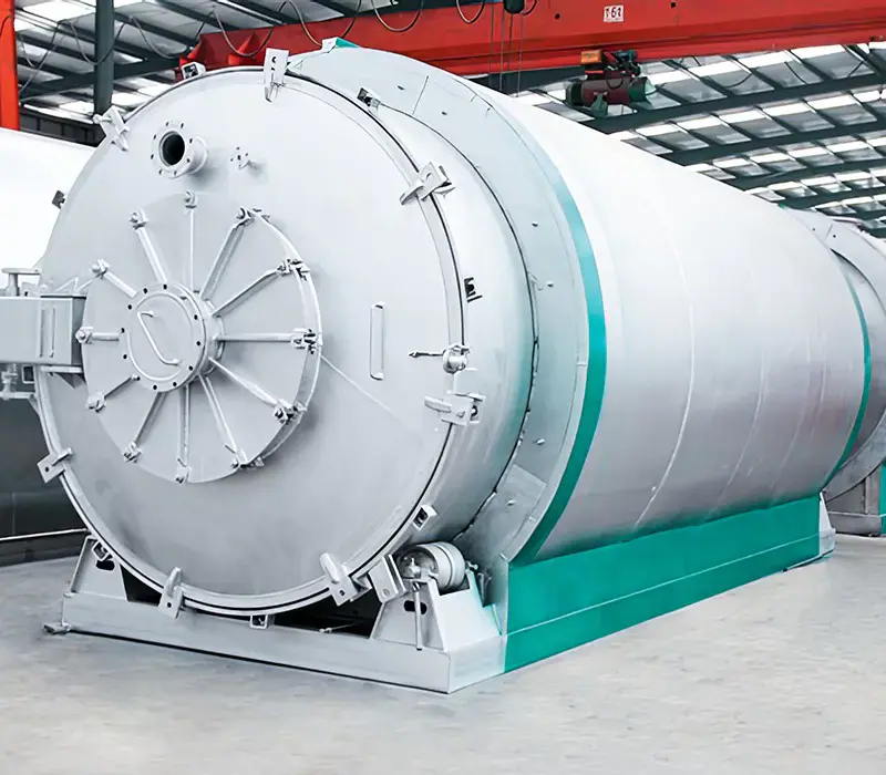
Batch waste tyre equipment

Batch Tyre Pyrolysis Plant

Review a batch tyre pyrolysis plant for whole or prepared waste tyres, including cycle operation, condensation, gas handling and project requirements.

2026-07-20
Request a quote
Batch tyre project fit

Choose the operating mode from feed supply and the real operating calendar

Batch and continuous plants are not separated by one universal tonnes-per-day threshold. Start with the annual tyre supply, delivery variability, prepared-feed window, planned working time and site interfaces, then compare configurations on the same basis.

Decision factorBatch operationContinuous operation

Feed supply

Batch operation

Can be evaluated for planned campaigns or variable deliveries when enough defined material is available for each charge and storage is managed.

Continuous operation

Usually depends on a stable stream of consistently prepared feed, plus buffer storage and a reliable feeding interface.

Operating rhythm

Batch operation

Runs through discrete charge, heat, hold, cool and discharge cycles, with opening and material handling between cycles.

Continuous operation

Uses sealed feeding, reaction and solids discharge during a planned run; shutdowns and restarts are managed by campaign.

Tyre preparation

Batch operation

Whole or larger tyre pieces may be possible only within the declared reactor, loading and steel-handling envelope.

Continuous operation

Generally needs a tighter and steadier size range, with shredding, screening, metal handling and buffering defined upstream.

People and controls

Batch operation

Staffing must cover loading, cycle checks, cooling, opening, discharge and safe changeover; automation level is configuration-specific.

Continuous operation

Integrated controls reduce repeated cycle handling, but operators are still required for preparation, control-room duty, solids handling and maintenance.

Site and utilities

Batch operation

Check cyclic utility peaks, cooling and discharge areas, inventory between cycles and safe access around the reactor.

Continuous operation

Check steady utility duties, linked preparation and discharge systems, buffer capacity, isolation points and maintenance access.

Maintenance and acceptance

Batch operation

Define inspection and cleaning triggers plus a complete-cycle test that includes non-reaction time.

Continuous operation

Define campaign length, stable-operation criteria, planned stops, cleaning windows and availability exclusions.

Batch is a candidate when

  • Tyre collection or deliveries are intermittent but can support planned charges.
  • The site and staffing plan can safely support discrete loading, cooling and discharge work.
  • A staged project or operating flexibility matters more than uninterrupted feed-through.
  • Capacity will be accepted from documented complete-cycle time, not reactor heating time alone.
Continuous is a candidate when

  • Prepared tyre feed can be supplied consistently over planned operating campaigns.
  • Shredding, screening, buffering and sealed feeding are included in the project boundary.
  • Utilities, controls, staffing and maintenance support an integrated line.
  • Hourly rate, annual throughput and availability will be tested on one declared feed basis.

Evidence needed before a model is selected

Send the same operating basis to every supplier so batch and continuous proposals can be compared without hidden assumptions.

  1. 01Twelve-month tyre source, quantity and delivery-variability record
  2. 02Representative feed samples, tyre form, moisture, contamination and steel content
  3. 03Operating days, shifts, shutdown windows and maintenance resources
  4. 04Plot plan, storage, utilities, fire protection and permit limits
  5. 05Required oil, recovered carbon, steel and residue specifications or destinations
  6. 06Contract test method: complete batch cycle or defined continuous stable run

Build the operating basis before requesting a configuration

Share feedstock evidence, the operating calendar, site conditions and acceptance method. Pyrojin can then compare batch and continuous options against the same declared project boundary.

Manufacturing evidence gate

Verify how a batch tyre plant is built, inspected and accepted

A product page cannot prove material traceability, weld quality or delivery readiness. Convert each claim into a project-linked record and a buyer acceptance point before fabrication starts.

Six evidence gates from fabrication release to service handover

Project-controlled record
01

Manufacturing dossier

Evidence record
Approved fabrication drawings, bill of materials, inspection and test plan, manufacturing traveler and controlled change log tied to the project number.
Buyer acceptance gate
Freeze the approved revision and hold points before cutting or forming; record and approve every deviation before the affected work proceeds.
02

Material traceability

Evidence record
Material certificates, heat or batch numbers, receiving checks and a traceability map from purchased material to identified pressure-retaining or critical parts.
Buyer acceptance gate
Reconcile grade, thickness, quantity and identifiers with the approved bill of materials; document substitutions and any agreed verification before use.
03

Welding and examination

Evidence record
Applicable WPS/PQR references, welder qualifications, weld map, fit-up and visual records, specified NDE results and a repair history linked to weld identifiers.
Buyer acceptance gate
Agree applicable code, examination extent, acceptance criteria and witness points; close nonconformities and repairs with traceable reinspection records.
04

Quality-control release

Evidence record
Dimensional reports, calibrated-instrument list, applicable pressure or leak-test records, coating or surface-preparation checks, nonconformity log and release status.
Buyer acceptance gate
Match inspections to the ITP and approved drawings; verify calibration validity, signed results and closure of open items before factory acceptance.
05

Factory and site acceptance

Evidence record
Agreed FAT and SAT protocols covering supplied scope, safeguards, instruments, cold functional checks, punch list, shipment release, commissioning interfaces and performance-test prerequisites.
Buyer acceptance gate
Define pass/fail criteria, feed and utility conditions, battery limits, exclusions, responsible witnesses and corrective-action deadlines before testing.
06

After-sales handover

Evidence record
Approved manuals, spare-parts list, maintenance schedule, training record, remote/on-site support scope, warranty boundary, response route and escalation contacts.
Buyer acceptance gate
Index the final dossier by equipment ID; confirm document language, training completion, spares receipt, support responsibilities and warranty start trigger at handover.

Request the evidence index with the quotation

Send the feed basis, site conditions and intended acceptance route. Ask the supplier to return a document index showing owner, planned issue date, review status and the project milestone controlled by each record.

This batch tyre pyrolysis page describes a cycle-based equipment route. Model capacity, cycle duration, output yields, utility demand, emissions performance and service life depend on the verified tyre feed, operating procedure, site configuration and acceptance conditions. Use the comparison and evidence checklist below before selecting a model.

How a Waste Tyre Batch Pyrolysis Plant Works

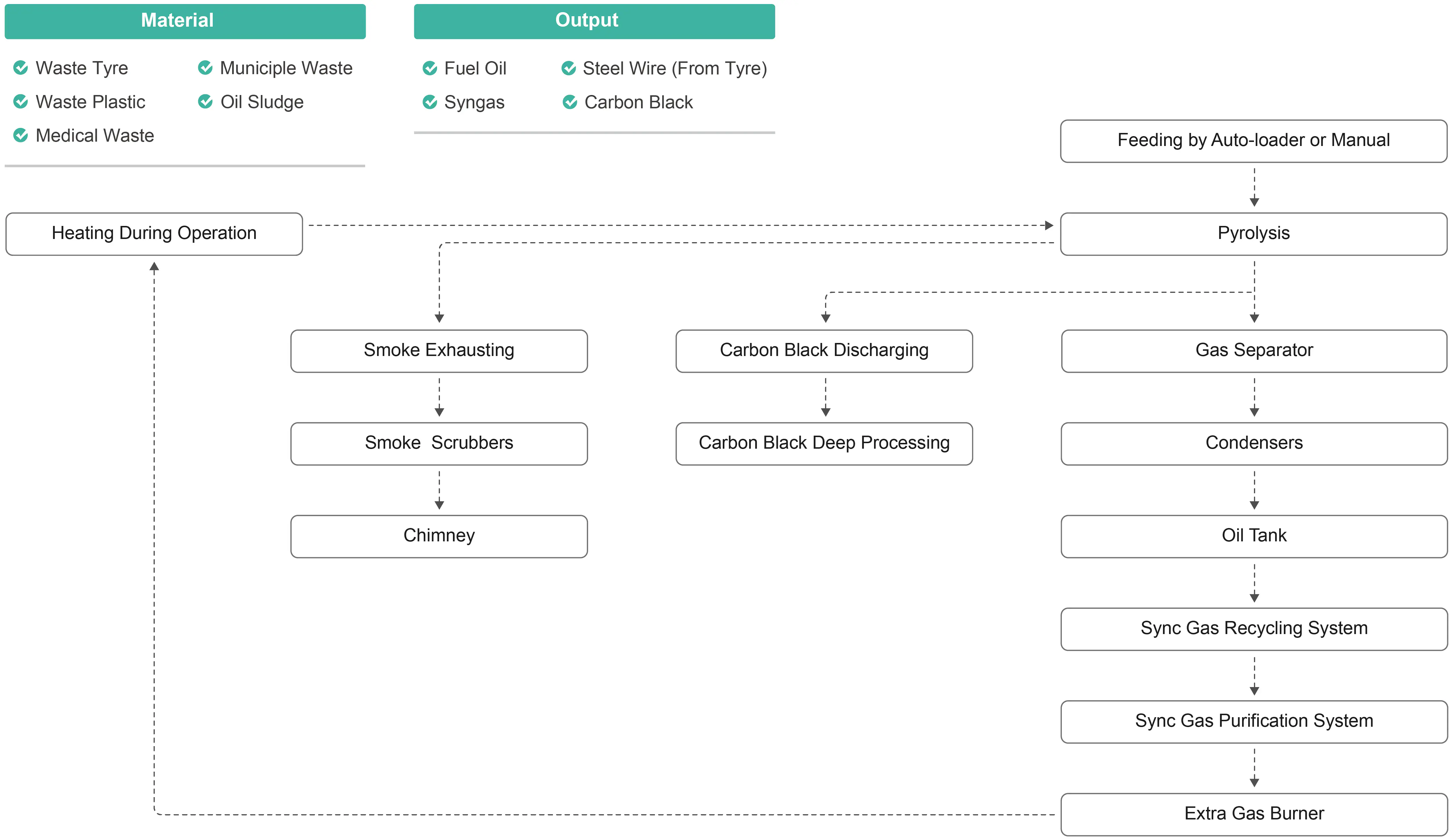
  1. Whole or shredded tyres are loaded into the horizontal rotary reactor.
  2. The reactor is sealed and heated indirectly in a low-oxygen environment, so flame never contacts the feedstock.
  3. Staged temperature control breaks the tyre polymer into oil vapour and non-condensable gas.
  4. The oil vapour is condensed into liquid fuel oil; the remaining gas is routed through a water-seal safety device back to the furnace for combustion.
  5. Flue gas passes through a spray tower for acid-base neutralisation (desulphurisation), then an adsorption tower, before discharge under the project's permitted limits.
  6. Solid residue is discharged as carbon black; the steel wire is separated by magnetic recovery (around 15% of tyre weight) and sold as scrap metal.

The system runs as a closed loop for resource recovery with no open-flame contact and controlled emissions.

Models and Specifications

ModelPB-10PB-12PB-15
Capacity10 t/day12 t/day15 t/day
Furnace sizeΦ2500×7500×18 mmΦ2500×8800×18 mmΦ2800×8800×18 mm
Gross weight53 t55 t60 t
Working power30-50 kW30-50 kW30-50 kW
Heating methodIndirect heatIndirect heatIndirect heat
Working typeBatchBatchBatch
Working pressureNormal pressureNormal pressureNormal pressure
Oil yield40-45%40-45%40-45%
Shipping1×FR + 2×40' HQ1×FR + 2×40' HQ1×FR + 2×40' HQ

Main reactor: thick-walled boiler steel with high-temperature annealing, rated for 10,000+ heating cycles. Rotation speed 0.4 rpm; circulating water cooling; noise ≤85 dB; installation footprint approx. 35 m × 20 m; 4-6 operators per shift.

Outputs and Yields

  • Fuel oil (40-45%) - used in industrial boilers, heavy equipment and generators, and can be further refined into diesel.
  • Recovered carbon black - feedstock for rubber, plastics and activated carbon.
  • Steel wire (≈15%) - recovered magnetically and sold as scrap metal.

Key Equipment Features

  • Low investment cost and compact footprint for fast payback.
  • External gear-ring drive for quiet, stable rotation.
  • Indirect heating for uniform temperature control and longer reactor life.
  • Combustible gas recycling to cut fuel consumption.
  • Fully sealed horizontal rotary design for clean, closed operation.
  • Slight negative pressure with automatic submerged-arc welding and ultrasonic NDT for safety.
  • Multi-furnace tandem operation to reduce heat loss.
  • Oil-gas fractionation tower separating fuel oil into three density grades.
  • Multi-stage flue-gas purification for acid neutralisation and dust removal.
  • High-temperature sealed slag discharge for enclosed carbon-black handling.

Applications

  • Tyre recyclers adding fuel-oil revenue to their existing operation.
  • Fuel suppliers producing pyrolysis oil for boilers, generators and further refining.
  • Industrial operators recovering steel wire and carbon black as saleable by-products.
  • Municipal or regional waste-to-resource projects.

Frequently Asked Questions

  • What is the delivery time? The delivery schedule and departure port are confirmed in the commercial quotation.
  • What payment methods do you accept? Mainly T/T; other methods on request.
  • Are you a factory or a trading company? We operate our own factory in Shangqiu, Henan, China.
  • Do you provide installation support? Installation, commissioning, training, warranty and maintenance support are defined in the supply contract.
  • What information do I need for a quote? Raw material, daily processing volume, project location and target outputs.

Get a Configuration Quote

Tell us your feedstock, daily volume and project location, and a Pyrojin engineer will prepare a matching configuration, layout and investment estimate.

Batch waste tyre equipment

Compare batch operation with continuous tyre processing

A batch tyre pyrolysis plant processes a defined charge through loading, heating, condensation, cooling and discharge stages. The preferred route depends on tyre preparation, daily volume, labour plan, site utilities and the required output handling system.

Tyre project pathway

Continue through the tyre pyrolysis evidence chain

Move between equipment selection, preparation, project records and downstream processing without losing the project context.

Project Verification Passport

Confirm performance boundaries before contract

Project enquiry

Need configuration advice for your feedstock?

Contact Pyrojin