
Subtitle: A ten-unit, 120 TPD design-capacity batch pyrolysis site in Chifeng, Inner Mongolia, organized around phased batch scheduling, shared utilities, rotated solids discharge, and a crew structure built for cyclic rather than constant attention.
Project Details
- Project Location
- Chifeng, Inner Mongolia, China
- Configuration
- 10 × XY-8-P/PB batch-type horizontal rotary pyrolysis units
- Combined Design Capacity
- 120 TPD (10 × 12 TPD per-unit design capacity, batch)
- Feedstock
- Waste tires
- Project Year
- 2018
- Original Project Status
- Delivered and commissioned in 2018
- Current Operating Status
- Not independently verified
- Supplier
- Shangqiu Jinpeng Industrial Co., Ltd.
Opening
Ten batch reactors change what the word "batch" means on a site. One unit follows a roughly 24-hour cycle of loading, heating, pyrolysis, cooling, and discharge, and a single plant is a simple schedule. Ten units at 12 TPD design capacity each - a combined design capacity of 120 TPD - pose a different problem. At this scale the batch cycle has to be orchestrated so that ten reactors share one site's utilities, one material-handling function, and a crew that cannot simply be ten times the size of a single-plant crew. The interesting question in this 2018 Chifeng archive project is therefore organizational as much as technical: how a large batch site is phased, how its utilities are shared, how solids discharge is rotated, and how labor is structured across ten lines so that added scale does not multiply labor and infrastructure in proportion.
Project Background & Configuration Logic
The documented configuration is ten 12 TPD batch pyrolysis units delivered and commissioned in 2018 in Chifeng, Inner Mongolia, processing waste tires. The choice of ten batch units rather than a continuous line reflects the feedstock and the site's production logic. Batch plants accept whole or cut tires loaded directly into the reactor, so the upstream chain is tire collection and sorting rather than crumb production; a continuous plant of comparable scale would require pre-processing the feedstock to rubber crumb. Ten identical units also bring operational flexibility: lines can be brought into service progressively, and a maintenance stop on one reactor does not stop the site.
At this scale, site infrastructure dominates the design. A ten-unit site concentrates cooling water, flue-gas treatment, non-condensable gas handling, control, and product storage at one address, so the configuration was designed around the utilities and the schedule as much as around the reactors themselves. The organizing principle is that ten units operate as one managed site rather than ten independent plants: phases are staggered, utilities are shared and sized for realistic overlap, and handling functions are rotated across the lines. A northern Inner Mongolia location also brings cold-season considerations into the utility design, notably for cooling-water and condensation systems, though the documented record for this project covers the delivered configuration rather than seasonal operating history.
Core Technology & Production Analysis
Each XY-8-P/PB unit is a horizontal rotary reactor, indirectly heated, operating under micro-negative pressure with an inert atmosphere during the pyrolysis phase; slow rotation (on the order of 0.4 r/min) keeps the material exposed to the heated shell. The per-unit cycle - loading, preheat, pyrolysis, cooling, discharge - runs in the region of 22-24 hours at design conditions. On a ten-unit site, five aspects of organization carry the production logic.
Phasing the batch cycle
The organizing principle of the site is phasing: reactor start times are staggered so that process stages do not coincide across all ten lines. At any given hour, some reactors are in pyrolysis, some in cooling, and one or two at loading or discharge. Phasing spreads demand for heat, cooling water, and operator attention across the day rather than concentrating it, and it gives the site a steadier output profile than the raw batch cycle would suggest. The schedule only works if utilities and handling capacity are sized for the overlapping stages, which is why phasing is a design feature of the site rather than a scheduling afterthought.
Shared utility architecture
What makes ten units one plant is the utility layer. The cooling-water circuit is sized for the realistic worst-case overlap of cooling phases rather than for ten simultaneous cool-downs. Flue gas from the units is routed to the installed treatment system - a spray tower with alkali scrubbing and an adsorption tower for desulfurization and dedusting - designed to meet local emission requirements under proper operating conditions. Non-condensable gas from the process may be returned to the heating system where the installed design and operating conditions permit, potentially reducing the site's external fuel demand. A shared control point allows operators to supervise groups of reactors, since much of the cycle is unattended pyrolysis time under monitoring.
Discharge rotation and solids handling
Each completed batch yields pyrolysis oil plus two solid streams: recovered carbonaceous material and steel wire. If all ten reactors discharged at once, solids handling would need ten times the labor and storage in a short window. With phased cycles, discharge events arrive at intervals, and a single material-handling function can rotate between lines - cooling the discharged solids, moving them to storage, and separating the steel wire for recycling. At this scale, discharge rotation is as much a production-planning matter as the loading schedule, because the recovered carbonaceous material is a solid product with its own handling, storage, and dispatch requirements.
Labor structure across ten lines
The XY-8-P/PB line is designed around PLC-controlled operation with a small operator presence per plant. Across ten lines, the crew structure follows the cycle: attention is concentrated where people are actually needed - loading, ignition and preheat checks, discharge, and product handling - while the pyrolysis phase runs largely unattended under supervision. The practical organization is therefore a team arranged by function: line operators covering groups of reactors from the shared control point, material-handling staff for loading and discharge, and a maintenance function for the rotating vessels, drives, and treatment systems. Installation guidance and operator training were part of the delivery scope.
Intake, storage, and feedstock flow
Ten units at 12 TPD design capacity consume a large, continuous intake of waste tires. The site needs tire storage that absorbs irregular collection arrivals, an intake area matched to the loading slots of the phased schedule, and protected storage where local conditions require it. Because the process accepts whole or cut tires, the feedstock chain is collection, sorting, and sizing rather than crumb production. The storage and intake layout is part of the organizational design: intake must feed the schedule, not the other way around.
Photo 1
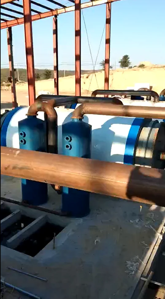
Overall view of the ten-reactor batch pyrolysis site in Chifeng, Inner Mongolia, showing the reactor row and shared site infrastructure. Photo taken during installation and commissioning in 2018.
Photo 2
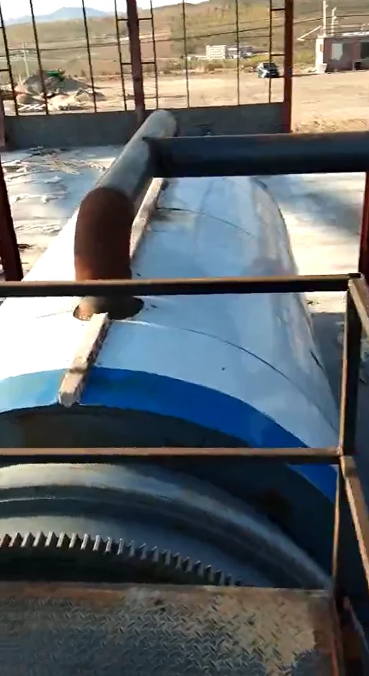
Process detail of a batch pyrolysis unit at the Chifeng site, showing the horizontal rotary reactor and its supporting systems. Photo taken during installation and commissioning in 2018.
Project Specifications
| Item | Project specification |
|---|---|
| Location | Chifeng, Inner Mongolia, China |
| Project year | 2018 |
| Status | Historical archive project - delivered and commissioned in 2018; current operating status not independently verified |
| Feedstock | Waste tires (whole or cut, loaded in batches) |
| System | Batch-type pyrolysis (XY-8-P/PB horizontal rotary reactors; indirect heating; micro-negative pressure; inert atmosphere) |
| Number of units | 10 |
| Capacity per unit | 12 TPD design capacity (batch) |
| Combined design capacity | 120 TPD (10 × 12 TPD, batch) |
| Production model | Phased batch scheduling across ten lines; shared cooling-water, gas, and flue-gas treatment utilities; rotated solids discharge |
| Main recovered streams | Pyrolysis oil (fuel oil), recovered carbonaceous material, steel wire; non-condensable gas may be returned to the heating system where the installed design and operating conditions permit |
| Supplier | Shangqiu Jinpeng Industrial Co., Ltd. |
What the Project Demonstrates
This archive project demonstrates the organizational side of large batch sites: ten reactors operating as one managed site through phasing, shared utilities, and discharge rotation, with a crew structure built around cyclic attention rather than one full team per reactor. For clients considering multi-unit scale, the reference value lies in what the configuration shows about the difference between owning ten reactors and running a ten-unit schedule. Evaluators should watch the sizing of shared utilities for simultaneous process stages, intake and solids storage capacity, the staffing model, and the site's compliance obligations - scale in batch pyrolysis is a scheduling and infrastructure problem as much as an equipment problem.
About Jinpeng
Shangqiu Jinpeng Industrial Co., Ltd. designs and manufactures batch, semi-continuous, and continuous pyrolysis plants, oil distillation systems, and supporting equipment for waste tires, waste plastics, oil sludge, rubber-derived materials, and other suitable carbon-rich feedstocks. Project configuration is developed around material characteristics, production objectives, site conditions, and applicable local requirements. For project discussions, visit www.pyrolysis-machine.com.
Disclaimer
This article describes a historical archive project and does not verify the plant's current operating status. All capacities are design values; actual throughput depends on feedstock quality and operating conditions. Product yields and properties - including the recovered carbonaceous material and the pyrolysis oil - must be established by testing of the actual feedstock and the installed process. Energy and emissions performance depends on the auxiliary systems, the installed treatment equipment, and actual operation, and the final design must comply with local regulations and emission requirements.
Archive Note: This retrospective is based on Jinpeng's project records and photographs from the original delivery and commissioning period. It describes the documented project configuration and does not constitute verification of the plant's current operating status.