
Project Details
| Field | Detail |
|---|---|
| Project Location | Yuncheng, Shanxi Province, China |
| Configuration | 6 × batch-type horizontal rotary pyrolysis units (12 TPD design capacity per unit) |
| Combined Design Capacity | 72 TPD (6 × 12 TPD, design value) |
| Feedstock | Waste tires (whole or cut) |
| Project Year | 2017 |
| Original Project Status | Delivered and commissioned in 2017 |
| Current Operating Status | Not independently verified |
| Supplier | Shangqiu Jinpeng Industrial Co., Ltd. |
Opening
The difference between a batch plant and a batch operation is organization. A single reactor is a self-contained machine: load it, heat it, cool it, empty it. Six reactors are something else - a production system in which the interesting engineering lies not in any one unit but in how the units are arranged around shared utilities, a staged loading schedule, and a steady feedstock flow. This archive project from Yuncheng, Shanxi, documents that arrangement: a 6 × 12 TPD batch waste-tire installation from 2017, with a combined design capacity of 72 TPD, sited in central-north China.
Project Background & Configuration Logic
The configuration was designed to convert a continuing intake of whole tires into a steady series of completed batches. In 2017 the batch model was the established production technology, and six 12 TPD lines were a way to reach meaningful site scale without leaving the batch model: whole-tire loading keeps feedstock preparation modest, each line runs with one or two operators, and capacity can be phased in as intake builds. Because the six units share one site, the support systems could be engineered once for the combined load - cooling water, fuel and gas return, flue-gas treatment, and product storage - rather than six times over. That is the economic logic of a multi-unit batch site.
Core Technology & Production Analysis
Six reactors, one utility spine
Each of the six lines is a batch-type horizontal rotary reactor, heated indirectly so that the material does not come into direct contact with the flame, running at low pressure under an inert, anaerobic atmosphere at slight negative pressure - the standard design basis of the PB (XY-8-P) series. What makes the site a system rather than a row of machines is that shared spine. Cooling water circulates in a site-wide circuit; the heating arrangement draws on a common fuel supply, supplemented where the installed design and operating conditions permit by non-condensable gas returned from the process; and the flue-gas stream of the whole site is routed to a shared treatment train. Sizing those shared systems for the combined load - rather than for six coincident peaks - is where a multi-unit batch site earns its economics.
Staged loading and the batch rotation
Each reactor follows a batch cycle spanning roughly 22 to 24 hours as a design reference: loading, preheating, pyrolysis, cooling, and discharge. If six reactors ran the same clock, the site would have six simultaneous peaks of every kind. The configuration instead staggers the lines so that at any moment one reactor is being loaded, two or three are in their pyrolysis phase, one is cooling, and one is being discharged. Staged loading has three production effects: it smooths demand on the shared utilities, it keeps the loading and discharge crew steadily occupied instead of working in bursts, and it spreads the gas and vapor stream across the day so downstream treatment sees a steadier load.
Feedstock flow and intake cadence
Whole tires arrive at the site and are held in a stockyard before preparation. The stockyard is not a side facility but part of the production logic: because the six reactors consume tires in rotation, intake is a continuous, site-level activity while loading remains per-batch, and the yard must buffer deliveries against the site's daily consumption. Before loading, tires are sorted and, where needed, cut to suit the reactor opening. Preparation feeds whichever reactor is in its loading window, so the preparation area and the loading schedule are planned together - a point worth watching, since a mismatch between intake cadence and batch consumption either starves the rotation or buries the yard.
Per-line condensation, site-level product handling
Each reactor condenses its own vapor stream, and products are collected per batch: pyrolysis oil - a fuel oil, not a diesel product, since reaching diesel specification would require further distillation, hydrotreating, and certification testing - along with recovered carbonaceous material and steel wire. While recovery is per-line, storage and dispatch are organized at site level. For a six-unit plant this is a practical choice: oil from several completed batches can be consolidated into a single holding tank and dispatched in full loads, while the recovered carbonaceous material and wire accumulate at collection points sized for the combined throughput. Product boundaries are part of the configuration logic: the solid stream is recovered carbonaceous material, not a commercial-grade carbon black unless it is deep-processed and tested.
Gas return and the shared flue-gas treatment train
Non-condensable gas from the process may be returned to the heating system where the installed design and operating conditions permit, which reduces the site's demand for purchased fuel. Flue gas from the combined site is treated after the installed treatment system - a spray tower with alkali solution and an adsorption tower for desulfurization and dust removal - designed to meet applicable local emission requirements under proper operating conditions. The staged loading schedule supports this design: by keeping the six reactors from finishing their pyrolysis phases simultaneously, it keeps the gas stream steadier, so the treatment train does not have to be sized for six coincident peaks.
Operating and maintenance flexibility
Because the six lines are independent batch units, the site can take one reactor offline for maintenance or inspection while the remaining lines continue to run - an advantage of a multi-unit batch configuration over one large unit, and a reason batch sites grow by adding lines. The labor model follows the rotation: one or two operators per plant, with the site crew organized around the loading, discharge, and monitoring windows created by the staggered schedule. This 2017 installation is an early record of that multi-unit organization, and the same logic - shared utilities, staged loading, continuous feedstock flow - appears again in the larger batch sites that followed.
Photo 1
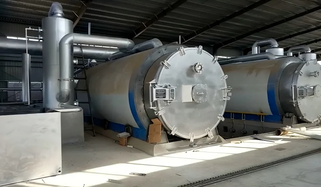
Overall view of the six-unit batch waste-tire pyrolysis plant in Yuncheng, Shanxi, showing the arrangement of the reactor lines and the shared site utilities. Photo taken during installation and commissioning in 2017.
Photo 2
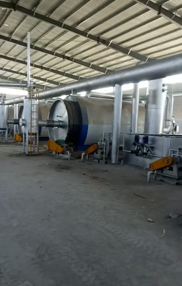
Process detail at the Yuncheng plant - the tire preparation and loading area that feeds the staged loading schedule of the six reactors. Photo taken during installation and commissioning in 2017.
Project Specifications
| Item | Project specification |
|---|---|
| Location | Yuncheng, Shanxi Province, China |
| Project year | 2017 |
| Status | Archive project - delivered and commissioned in 2017; current operating status not independently verified |
| Feedstock | Waste tires (whole or cut) |
| System | PB (XY-8-P) series batch-type horizontal rotary pyrolysis |
| Number of units | 6 |
| Capacity per unit | 12 TPD (design) |
| Combined design capacity | 72 TPD (design) |
| Production model | Batch, with staged loading across six lines |
| Main recovered streams | Pyrolysis oil (fuel oil), recovered carbonaceous material, steel wire; non-condensable gas may be returned to the heating system where the installed design and operating conditions permit |
| Supplier | Shangqiu Jinpeng Industrial Co., Ltd. |
What the Project Demonstrates
This archive project demonstrates that a multi-unit batch site is organized as a production system, not as a row of independent machines. The value of the record is concrete: shared utilities sized for the combined load, a staged loading schedule that smooths the peaks every batch creates, and a feedstock flow planned around the site's consumption cadence. For operators planning to grow beyond one or two units, the points to watch are the same ones this configuration had to solve: whether cooling water and the treatment train are sized for the combined stream, whether the rotation keeps crew and utilities evenly loaded, and whether stockyard capacity matches intake cadence. For evaluators, the archive shows the pattern later, larger batch sites build on: scale achieved by organizing batch units well, not by abandoning the batch model.
About Jinpeng
Shangqiu Jinpeng Industrial Co., Ltd. designs and manufactures batch, semi-continuous, and continuous pyrolysis plants, oil distillation systems, and supporting equipment for waste tires, waste plastics, oil sludge, rubber-derived materials, and other suitable carbon-rich feedstocks. Project configuration is developed around material characteristics, production objectives, site conditions, and applicable local requirements. For project discussions, visit www.pyrolysis-machine.com.
Disclaimer
All capacities in this article are design values. Actual throughput depends on feedstock characteristics and operating conditions; recovered yields and product properties must be established by testing of the specific feedstock; energy consumption and emissions performance depend on the auxiliary systems installed and on actual operation; and the final design must comply with applicable local regulations.
Archive Note: This retrospective is based on Jinpeng's project records and photographs from the original delivery and commissioning period. It describes the documented project configuration and does not constitute verification of the plant's current operating status.